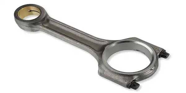
How To Check And Repair Engine Connecting Rods
When the connecting rod is in use, the shaft will be bent and twisted, the bushing and the shaft will be damaged, etc.
①Bending Detection
Install the connecting rod on the support shaft and tighten with standard torque, and install the repaired piston pin. Set the connecting rod bearing hole on the horizontal shaft of the tester, turn the shaft end screw to make the centering block on the horizontal shaft stretch out, and fix the connecting rod on the tester. Place the V-shaped surface of the small angle iron of the tester against the top surface of the piston pin and tighten the small angle iron fixing screw. By observing the contact between the three claw heads of the small angle iron and the plane, the connecting rod can be found out.
Bending direction and extent. It is also possible to install two shafts with the same diameter as the connecting rod journal and the live cold pin respectively in the large and small head holes of the connecting rod, and erect the connecting rod with the big end facing down, and support it in two equal "V" shaped irons. , "V" shaped iron on the plate. Use the bracket to support the dial indicator on the top of the connecting rod, place the bracket on the flat plate, and use the dial indicator to measure the height difference between the two ends of the pin shaft 100mm apart, which is the bending degree. If the curvature exceeds 0.05mm, it should be corrected.
In addition to the popular science of the connecting rod, click here to learn about the daily maintenance knowledge of the fuel pump.
②Distortion Check
On the basis of the bending inspection, move the small angle iron down to make its side contact, and observe the contact between the small angle iron and the two ends of the piston pin, and then the twisting direction and the amount of twisting can be measured. It is also possible to install two shafts with the same diameter as the connecting rod journal and the piston pin respectively in the large and small holes, and place the connecting rod horizontally on the "V"-shaped iron on the flat plate, and use it to support the bracket on the bracket. Measure the height difference between the two-point cylinders with a distance of 100mm between the two ends of the pin shaft, which is the twist degree. When the distortion is greater than 0.01mm, it should be corrected.
③ Correction of Connecting Rod Bending
Put the connecting rod into the corrector, with the curved convex side facing upwards, place a pad on the place where the connecting rod is under pressure, turn the screw on the corrector with a wrench, and press the small end of the connecting rod to bend it upwards, hold it for a certain period of time and release it screws and remove the connecting rod. To prevent elastic failure, the connecting rod can be heated slightly with a blowtorch. After the connecting rod is calibrated, it should be re-inspected.
④Correction Link Twist
Turn the handle of the corrector to bend the connecting rod in the direction of correction, release the pressure after maintaining the pressure for a period of time, and use a blowtorch to heat the connecting rod slightly. Re-check after calibration, if it does not meet the requirements, re-calibrate.
 Track Your Order


